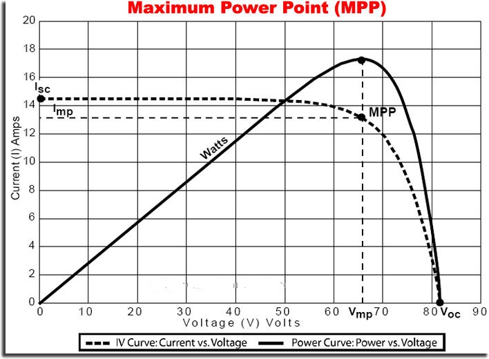
When a solar PV module is used in a system, its operating point is decided by the load to which it is connected. Also since solar radiation falling on a PV module varies throughout the day, the operating point of module also changes throughout the day. When a PV system is deployed for practical applications, the I-V characteristics keeps on changing with insolation and temperature. For example the operating point of a PV module and a resistive load for 12 noon, 10 am and 8 am will vary from each other, and under all the operating conditions it is desirable to transfer maximum power from a PV module to the load. In order to receive maximum power, the load must adjust itself accordingly to track the maximum power point. In order to ensure the operation of PV modules for maximum power transfer a special method called Maximum Power Point Tracking (MPPT) is employed in PV systems. MPPT is not the same as the mechanical tracking (sun tracking) of solar PV modules. In sun tracking method, PV modules are mechanically rotated so the radiation is maximum while in the case of MPPT, electronic circuitry is used to ensure that maximum amount of generated power is transferred to the load. Figure below shows the maximum power point curve.
MPPT Curve
The maximum power tracking mechanism makes use of an algorithm and an electronic circuitry. The mechanism is based on the principle of impedance matching between load and PV module, which is necessary for maximum power transfer. Generally MPPT is an adaptation of DC to DC switching voltage regulator. The impedance matching is done by using a DC to DC converter. Using a DC to DC converter the impedance is matched by changing the duty cycle of the switch. Coupling to the load for maximum power transfer may require either providing a higher voltage for higher current. A buck boost scheme is commonly used with voltage and current sensors tied into a feedback loop using a controller to vary the switching times. Buck converter can also be used. The block diagram of an MPPT algorithm is shown in below figure.

Block diagram of MPPT algorithm
The power from the solar module can be calculated by measuring the voltage and the current. This power is an input to the algorithm which then adjusts the duty cycle of the switch, resulting in the adjustment of the reflected load impedance according to the power output of PV module. For instance the relation between the input voltage(Vi) and the output voltage (Vo) and the impedance of load (RL) reflected at the input side (Ri) of a buck type DC to DC converter can be given as,
Where d is the duty cycle. By adjusting the duty cycle, Ri can be varied which should be same as the impedance of solar PV module (RPV) in a given operating condition for maximum power transfer.
The power output of a PV system is given by,
With incremental change in current and voltage, the modified power is given by,
This after ignoring small terms simplifies to,
δP must be zero at break point. Therefore at peak point the above expression in the limit becomes,
It may be noted here that dV / dI is the dynamic impedance of the source, which is required to be equal to negative of static impedance, V / I .
There are three possible strategies for the operation of an MPPT. They are:
Algorithms for MPPT are various types of schemes that are implemented for obtaining maximum power transfer. Some of the popular schemes are incremental conductance method, system oscillation method, hill climbing method, modified hill climbing method, constant voltage method. Other MPPT methods include those which use state space approach with the tracking power converter operating in Continuous Conduction Mode (CCM) and the another one which is based on a combination of incremental conductance and perturb and observe method. Energy extracted from the PV source through MPPT should be either utilized by a load or stored in some form for example, energy stored in a battery or used for electrolysis to produce hydrogen for future use in fuel cells. In view of this grid connected PV systems are very popular as they do not have any energy storage requirements since the grid can absorb any amount of PV energy tracked.
Some of the popular and most commonly used MPPT schemes are explained below:
Constant voltage method: The ration of VMPP and Voc is a constant approxiately equal to 0.78. Here array voltage is represented by VMPP and the open circuit voltage is represented by Voc.The sensed PV array voltage is compared with a reference voltage to generate an error signal which in turn controls the duty cycle. The duty cycle of the power converter ensures that the PV array voltage is equal to 0.78 × Voc. Also Voc can be determined using a diode mounted at the back of the array (so that it has the same temperature as the array). A constant current is fed into the diode and the resulting voltage across the diode is used as the arrays Voc which then utilized in tracking VMPP.
Hill climbing method: The most popular algorithm is the hill climbing method. It is applied by perturbing the duty cycle ‘d’ at regular intervals and by recording the resulting array current and voltage values, thereby obtaining the power. Once the power is known, a check for the slope of the P- V curve or the operating region (current source or voltage source region) is carried out and then the change in d is effected in a direction so that the operating point approaches maximum power point on the power voltage characteristic.The algorithm of this scheme is described below along with the help of mathematical expressions,
As per the above equations if ∂PPV / ∂VPV is graeter than zero (Pnew > Pold) the duty cycle is increased (d = d + δd). This means that the slope is positive and the module is operating in the constant current region. In case of the slope being negative (Pnew < Pold) the duty cycle is reduced (d = d - δd), as the operating region in this case is the constsnt voltage region. This algorithm can be implemented using a microcontroller.
Incremental conductance method: In the Incremental conductance method, the maximum power point by matching the PV array impedance wit the effective impedance of the converter reflected across the terminals of the array. While, latter is tuned by increase or decrease in the duty cycle value. The algorithm can be explained as follows:
Incremental conductance MPPT method: Off-grid PV system are usually using batteries to supply loads at night. Although the fully charged battery pack voltage may be near to the maximum power point voltage of the PV panel's, this is not true at sunrise when the partial discharge of the battery takes place.At a certain voltage below the maximum voltage of the PV panel, charging takes place and this mismatch can be resolved using an MPPT. In case of a grid connected PV system, all the delivered power from solar modules will be sent to the grid. Therefore, the MPPT in a grid connected photovoltaic system will always try to operate the PV modules at its maximum power point.


Copyright © 2024 Mepits - Designed By Digiora

